Roller shutter control for up and down using Relay T2.
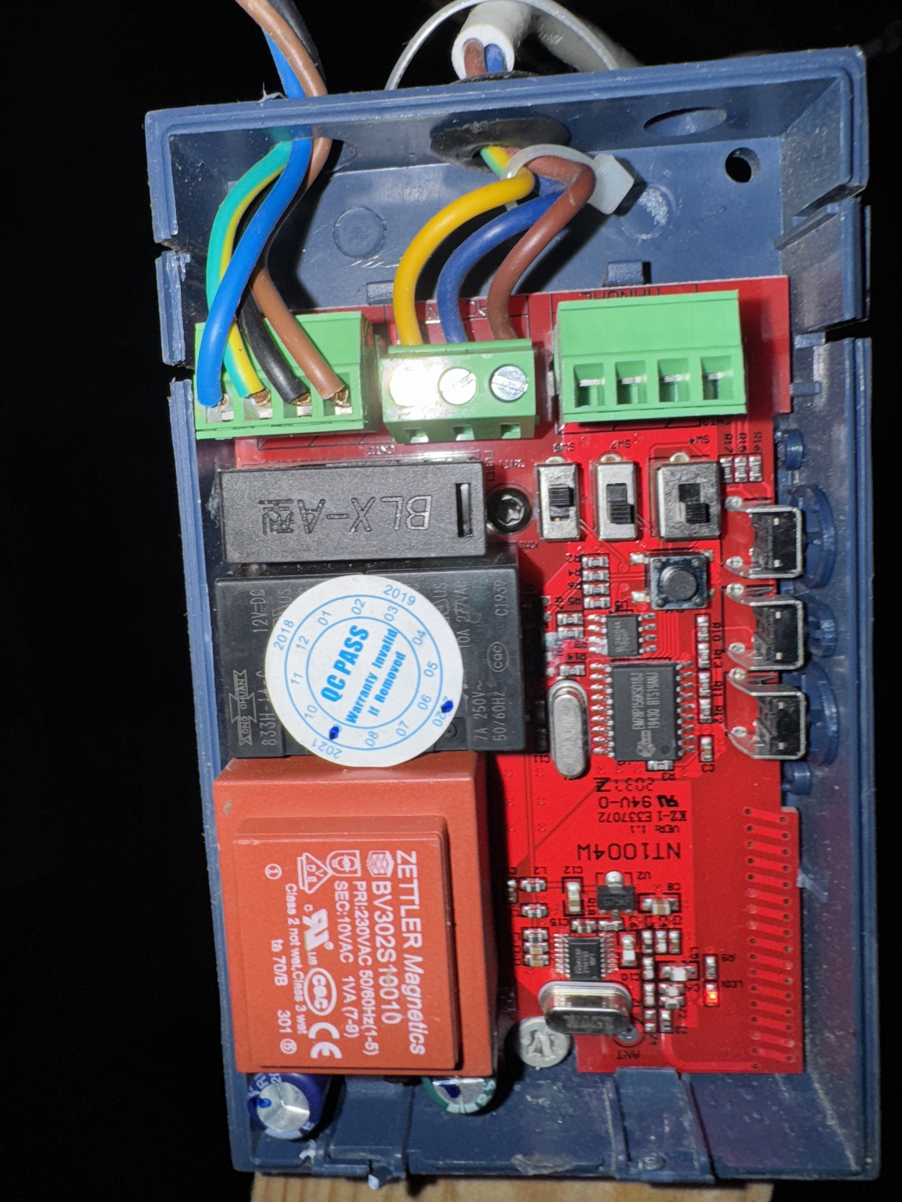
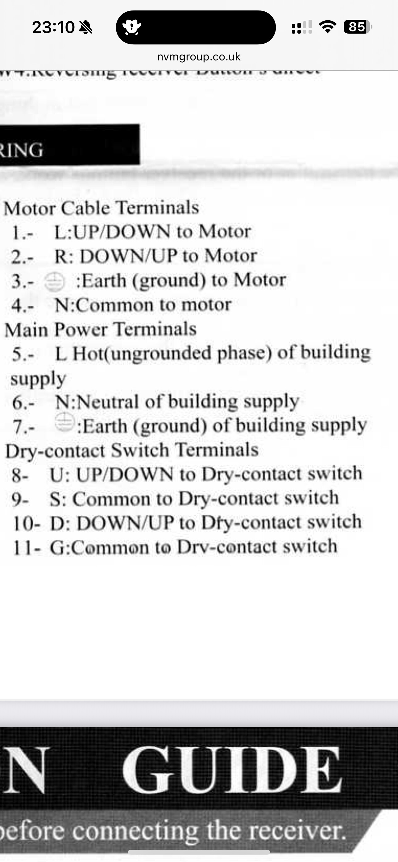
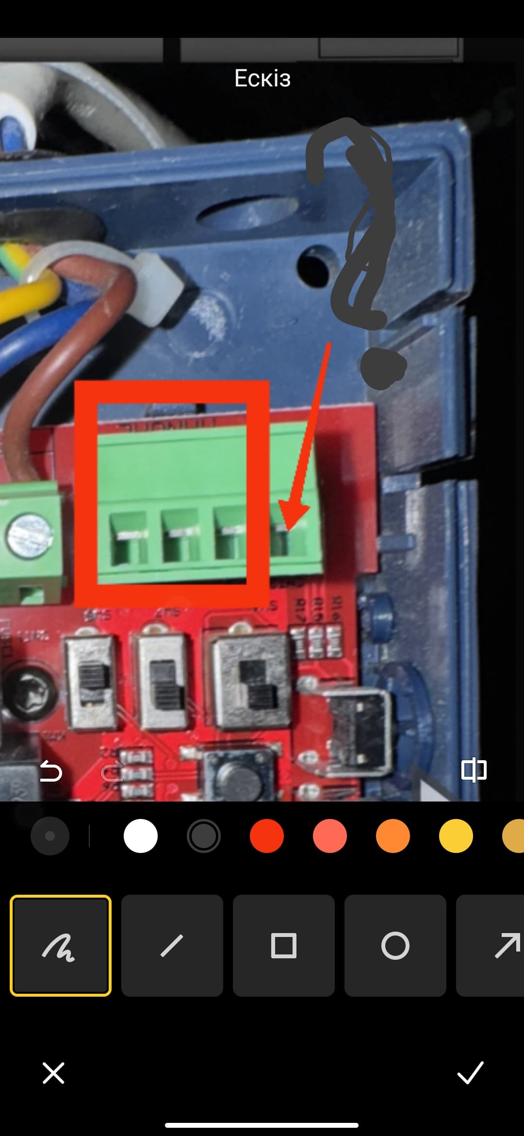
Attached images of the controller of my shutter, as well as the manual page relevant to the terminals to control the motor and a definition of what each terminal represents.
Would someone be able to tell me where I need to wire this up / how the relay is wired in to this.
Thanks!!
Hello, welcome to the forum. Theoretically, you need to use these contacts. Just in question is contact √11. Is there a descriptive part of the instructions with explanatory text? Please provide screenshots or PDF.
1 Like
Hello. Thanks for the help so far.
Here’s the PDF manual.
Thank you!
1 Like
Hello.
I looked at the description, unfortunately I did not find additional information that is needed for connection.
Part 1.
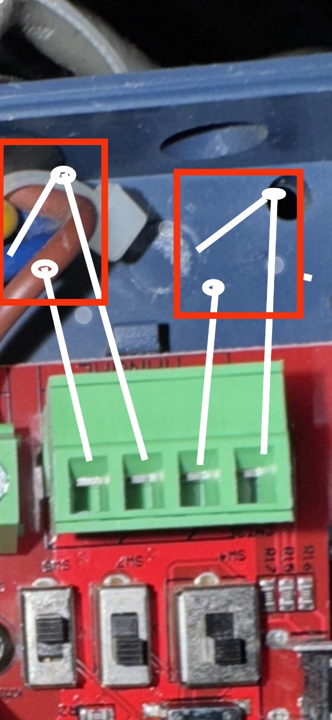
I suggest that you first, for the test, take two switches and connect them to points 8-9 and 10-11.
!!!I emphasize once again, two separate switches!!!
ATTENTION! All connections of switches should be made with the 220 volt equipment turned off.
After connecting the switches, you need to experiment with how the roller shutters will open (close).
Study their unlocking, how the process goes:
- turned on and off (roller shutters closed);
- did they turn on, wait for some time and turn off themselves when the roller shutters closed.
Figure 1 connecting the switches.
Figure 1.
Part 2.
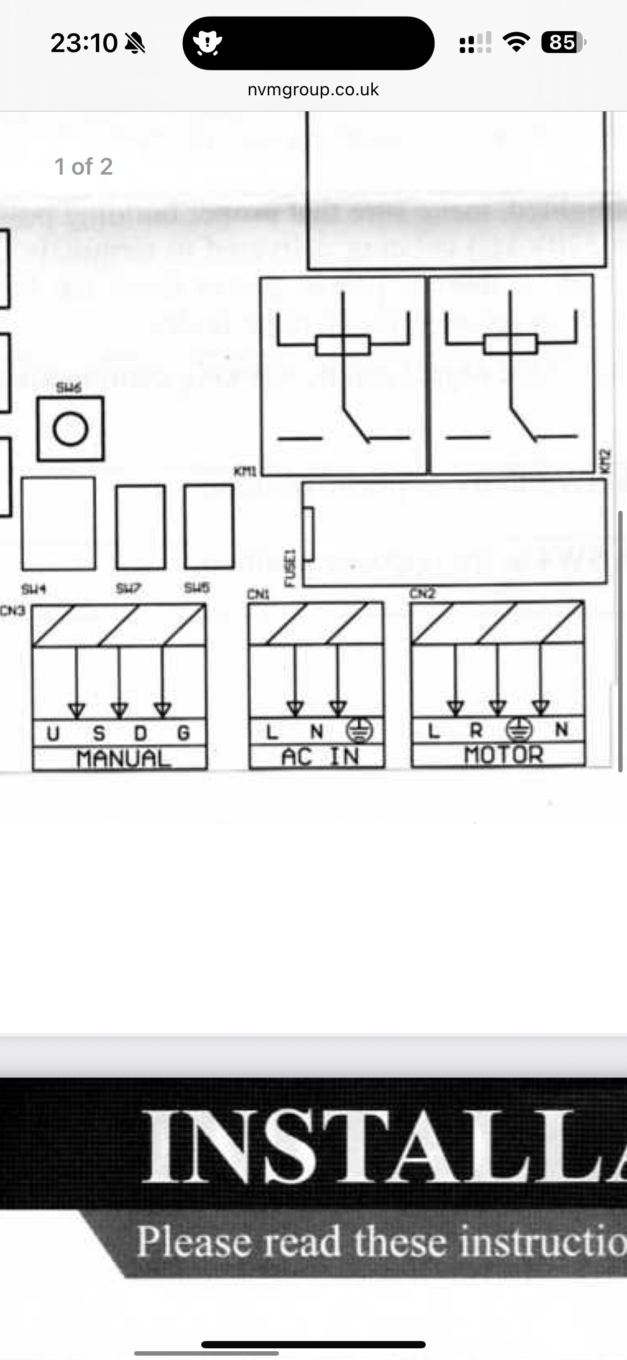
In your control circuit there is no common wire to the switch when manually controlled, there are two pairs of independent contacts 8-9, 10-11.
This connection scheme is not suitable for the T2 relay, in this relay the dry contacts have a common COM wire that sends a signal to L1 and L2.
To solve your problem, you need to install additional (intermediate) two 220 volt relays that will be controlled using the Aqara T2 relay (or the old-style Aqara relay). The T2 relay will operate in 220 volt mode and control the dry contacts of the additional (intermediate) relays.
If you understand what I described, then you will do it without a problem.
And if you do not understand, then write here, I will explain with a diagram and instructions for performing and connecting the equipment.
I emphasize once again that in order to start doing section 2, you need to check section 1.
Have a good day.
Hey!
Thanks once again for the help. I understand so much but the diagram and other bits you are suggesting to me would be good so that I can be sure what your instructions are.
Also, when you say switches to test for Part 1, what switches are you referring? The T2 or a normal light switch or a smart switch?
Thanks again, look forward to hearing from you and I can check it out.
2 Likes
Ordinary switch (dull). Needed only for studying the operation of contacts 8-9, 10-11.
Okay, fantastic! I’ll give it a go!
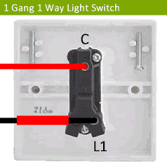
What are these bits that I have circled in black on your diagram? The switches just have the L1 and Com terminal.
Thanks!
Hi, yes, it is a regular dumb switch. L1+COM
Hey! Tested this and it turns out the following is the order:
S - STOP
G - Ground / Common
U - UP
D - DOWN
But where do I wire the COM / GROUND cable too from the shutter receiver on the T2 relay, that’s the question now.
Do you have any thoughts on this?
Hello, give me some time, I’ll reply later, I’m a little busy. Also tell me what the STOP signal means, how do you start it, I don’t understand. You have a general G. Describe the process in more detail.
If you have practice, try to draw a diagram of what you have connected. How all the buttons are used. Just use a pen on a piece of paper and take a picture.