Background
The Aqara W600 TRV is currently under active development, with the team working to improve temperature control performance. Many users have reported issues such as temperature overshoot, oscillations, and difficulty maintaining stable setpoint temperatures. These discussions have highlighted the critical importance of the control algorithm and its tuning.
This post aims to provide technical background on the different control approaches used in TRVs, explaining why certain behaviors occur and what trade-offs exist between different controller types. Understanding these fundamentals can help users interpret their TRV’s behavior and contribute more effectively to discussions about firmware improvements.
Smart thermostatic radiator valves (TRVs) are sophisticated devices that regulate room temperature by controlling the flow of hot water through radiators. The quality of temperature control depends heavily on the control algorithm used. This post explains the main approaches—from simple bang-bang control to advanced PI control—and discusses their respective advantages and limitations.
Understanding these control strategies can help explain why TRVs behave the way they do, and why some provide better temperature stability than others.
Controller Basics: The Control Loop
All TRV control algorithms operate on the same fundamental principle: the feedback control loop.
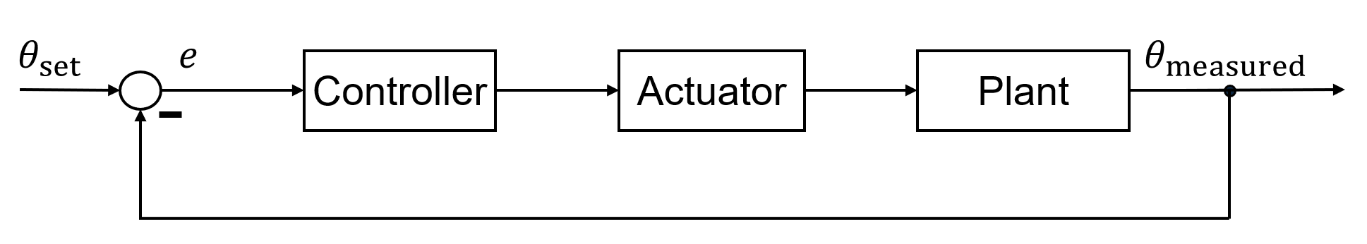
This closed-loop system continuously measures temperature and adjusts valve position to minimize the difference between the desired setpoint and actual room temperature.
Basic Control Loop Components
- Setpoint (theta_set): The desired room temperature selected by the user
- Measured Temperature (theta_measured): The current room temperature from the sensor
- Error (e): The difference between setpoint and measured temperature (e = theta_set - theta_measured)
- Controller: The algorithm that calculates the required valve position based on the error
- Actuator: The motor that physically opens or closes the valve
- Plant: The physical heating system (radiator + room) that responds to valve changes
The controller’s job is to determine the optimal valve position at each moment to bring the room temperature to the setpoint as quickly and smoothly as possible, while maintaining that temperature without oscillations or overshoot.
Bang-Bang Controller (On-Off Control)
The bang-bang controller is the simplest control strategy: the valve is either fully open or fully closed, with no intermediate positions.
How It Works
The controller uses a threshold (hysteresis band) to prevent rapid switching:
- If temperature drops below (theta_set - threshold): Valve opens completely
- If temperature reaches theta_set: Valve closes completely
Example: For a setpoint of 22°C with a 2K threshold:
- At 19.5°C (below 20°C): Valve fully opens
- At 22°C: Valve closes
- Temperature then drifts between 20°C and 24°C due to thermal inertia
Advantages
- Extremely simple to implement - minimal computational requirements
- Very low battery consumption (infrequent valve movements)
- Robust and reliable - no complex tuning required
- Works well for slow-responding systems with high thermal inertia
Disadvantages
- Temperature oscillations: Room temperature swings significantly above and below setpoint
- Overshoot: Radiator continues releasing heat after valve closes, causing temperature to exceed setpoint
- Large hysteresis band required to prevent frequent switching (up to 2-3°C), reducing comfort
- No proportional response: Cannot adapt to partial heating needs or changing conditions
- Inefficient energy use due to overheating cycles
Bottom line: Bang-bang control is acceptable for applications where some temperature variation is tolerable, but provides poor comfort compared to proportional control methods. You’ll typically find this approach in very simple, low-cost thermostats.
Proportional (P) Controller
The proportional controller represents a significant improvement over bang-bang control. Instead of binary on/off operation, the valve position is continuously adjusted in proportion to the temperature error.
How It Works
The control equation is straightforward:
u = K_P × e
Where:
- u: valve position (0 = closed, 1 = fully open)
- K_P: proportional gain (determines how aggressively the system responds)
- e = (theta_set - theta_measured): temperature error in °C
Example with K_P = 0.5:
- Error = 2°C below setpoint → valve opens 100% (2 × 0.5 = 1.0, saturated at maximum)
- Error = 1°C below setpoint → valve opens 50%
- Error = 0.5°C below setpoint → valve opens 25%
- At setpoint (error = 0) → valve closes completely
The key insight is that as temperature approaches the setpoint, the valve gradually closes, preventing overshoot. This “anticipatory” behavior is fundamentally different from bang-bang control.
Advantages
- Smooth, gradual control: Eliminates the temperature oscillations characteristic of bang-bang control
- No overshoot: Valve begins closing before setpoint is reached, preventing temperature from exceeding target
- Stable steady-state behavior: Temperature settles to a consistent value with minimal fluctuation
- Simple to tune: Only one parameter (K_P) needs adjustment
- Predictable behavior: Response is proportional and easy to understand
Disadvantages
- Steady-state offset: Cannot achieve zero error - room will typically settle 0.5-1°C below setpoint
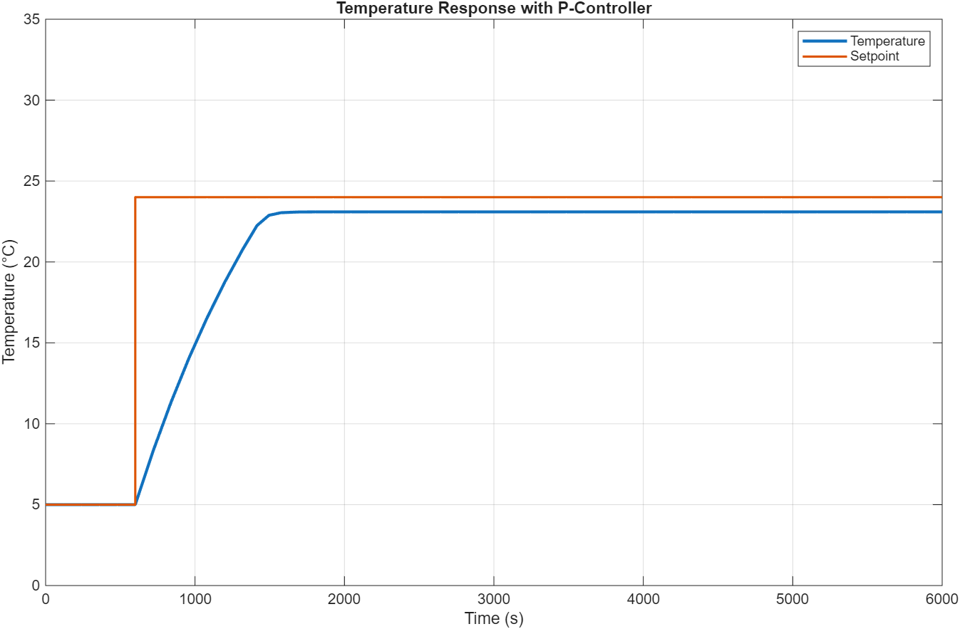
The steady-state offset occurs because at equilibrium, the heating power must exactly balance heat loss to the environment. Since P control only provides heating proportional to error, a small persistent error is required to maintain the necessary valve opening.
Example: Room settles at 21°C when setpoint is 22°C. With K_P = 0.5, the 1°C error produces u = 0.5 (50% valve opening), which provides just enough heat to balance the room’s heat loss at 21°C.
Bottom line: P control offers excellent stability and smooth operation with minimal complexity. The small steady-state offset is often acceptable for comfort heating applications and is far preferable to the temperature swings of bang-bang control. Many users find the predictable, stable behavior more comfortable than perfect setpoint accuracy with occasional overshoot.
Proportional-Integral (PI) Controller
The PI controller adds an integral term to proportional control, eliminating the steady-state offset while maintaining smooth control. This is the most sophisticated controller type commonly used in modern smart TRVs.
How It Works
The PI control equation combines two terms:
u = K_P × e + K_I × ∫e dt
Where:
- e = (theta_set - theta_measured) = current temperature error
- K_P = proportional gain (provides immediate response to error)
- K_I = integral gain (eliminates steady-state error by accumulating past errors)
The proportional term K_P × e provides immediate response based on current error, while the integral term K_I × ∫e dt accumulates error over time. If a small steady-state error persists, the integral grows until it provides enough additional valve opening to eliminate the error completely.
Advantages
- Zero steady-state error: Room temperature converges exactly to the setpoint
- Smooth control: When properly tuned, provides gradual, stable temperature regulation
- Better load rejection: Integral action helps compensate for changing conditions (outdoor temperature, sun, occupancy)
- Optimal for applications requiring precise temperature control
Disadvantages
- More complex to tune: Requires finding appropriate values for both K_P and K_I
- Can oscillate if parameters are too aggressive
- Higher computational requirements than P control
- Vulnerable to integral windup (see next section)
The Critical Problem: Integral Windup
Integral windup is the most significant challenge with PI control and can cause severe performance degradation if not properly addressed. It occurs when the actuator (valve) reaches saturation limits while the integral term continues accumulating error.
What Is Integral Windup?
Consider a cold start scenario: Room is at 5°C, setpoint is 24°C.
- Initial error: 19°C (very large)
- Controller immediately opens valve to 100% (saturated at maximum)
- Integral term continues growing: Even though valve can’t open further, the integral keeps accumulating the large error
- Room heats up: After several minutes, temperature reaches 23°C
- Problem: The integral term has accumulated to a huge value during saturation
- Result: Even though error is now small (1°C), the massive integral keeps valve fully open
- Consequence: Room temperature overshoots significantly to 31-32°C before valve finally begins to close
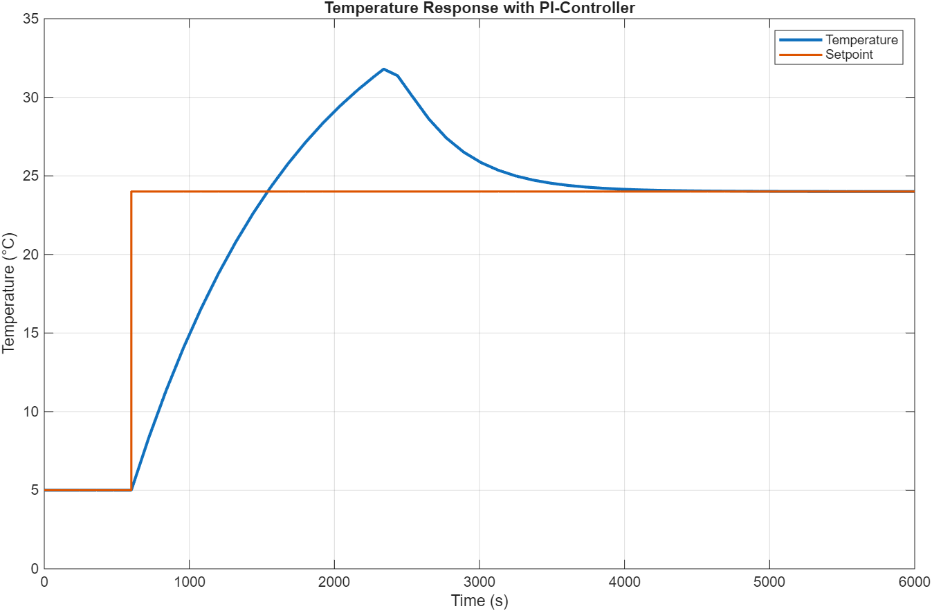
This is why some users experience their TRVs “shooting past” the setpoint temperature during heating from cold, especially on very cold days when the initial temperature error is large.
Why Aggressive Parameters Make It Worse
When K_I is too large (aggressive integral action), the windup problem becomes severe:
- Faster accumulation: The integral term grows rapidly during saturation
- Larger overshoot: More accumulated integral = longer period with valve stuck open
- Oscillations: After overshooting, the integral must “unwind” through negative errors, causing the system to oscillate
- Long settling time: Multiple oscillations before system stabilizes
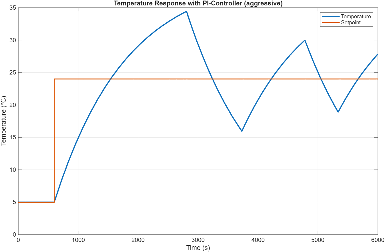
Users might notice this as the room temperature “hunting” around the setpoint - going too high, then too low, then too high again - before finally settling down after 30-60 minutes.
Anti-Windup Protection: Essential for Good PI Control
To prevent integral windup, well-designed PI controllers implement anti-windup protection. The most common method is conditional integration (clamping):
- Monitor actuator saturation: Detect when valve is at 0% or 100%
- Stop integration when saturated: If valve is fully open and error is positive (would make saturation worse), stop adding to the integral
- Resume integration when unsaturated: Once valve moves away from limits, normal integration continues
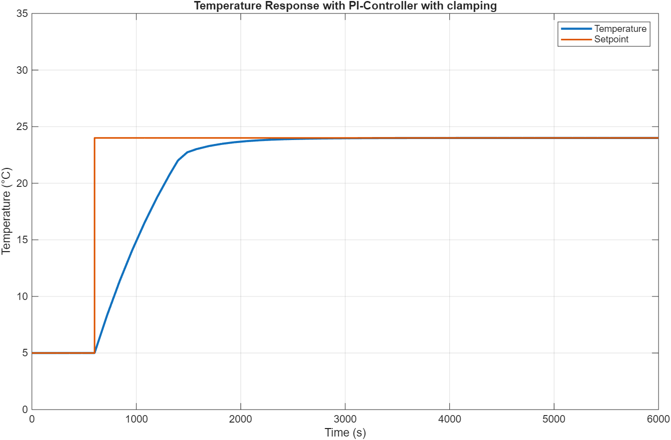
This protection mechanism prevents the integral from growing to unreasonable values during saturation, dramatically reducing overshoot and improving control quality.
What this means for users: If your TRV overshoots significantly or oscillates after setpoint changes, it may be using PI control without proper anti-windup protection, or the parameters may be tuned too aggressively. Firmware updates can improve control algorithm behavior significantly.
Comparison: What You Might Experience
Bang-Bang Control
What you’ll notice: Temperature varies noticeably (±1-2°C), especially when radiator first turns on. You might hear the valve clicking fully open and closed. Room feels alternately slightly cool and slightly warm.
Best for: Basic comfort needs where small temperature variations don’t matter.
Proportional (P) Control
What you’ll notice: Very stable temperature with minimal variation. Room might settle about 0.5-1°C below your setpoint (e.g., 21°C when you set 22°C), but stays there consistently. No overshoot, no oscillations.
Best for: Users who prioritize stability and predictability over hitting the exact setpoint. The small offset is usually imperceptible in terms of comfort.
Proportional-Integral (PI) Control
What you’ll notice:
- When well-tuned: Room reaches exactly the setpoint and stays there. Best of both worlds.
- When poorly tuned: May overshoot (28°C when you want 22°C), oscillate around setpoint, or take a very long time to settle. Cold starts can be particularly problematic.
Best for: Users who want precise temperature control and have a TRV with well-implemented PI control including anti-windup protection.
Conclusion
The choice of control algorithm significantly impacts TRV performance and user experience:
- Bang-bang control is the simplest but provides the least comfortable experience with noticeable temperature swings
- P control provides excellent stability and comfort with minimal complexity, trading a small steady-state offset for predictable, oscillation-free operation
- PI control can provide the best performance when properly implemented, but requires careful tuning and anti-windup protection to avoid overshoot and oscillations
If you’re experiencing temperature control issues with your TRV (overshoot, oscillations, slow response), understanding these control concepts can help you identify whether the issue is fundamental to the control algorithm being used, or whether it might be addressable through better tuning or firmware updates.
Explore the Simulations Yourself
If you’d like to experiment with these control algorithms and see how different parameters affect performance, I’ve uploaded the complete Simulink simulation files to GitHub. You can modify controller gains, test different scenarios (cold starts, setpoint changes, disturbances), and visualize the results yourself. This is a great way to develop intuition for how these controllers behave and why proper tuning is so important.
Feel free to play around with the simulations and share your findings!
Questions, comments, and feedback are welcome!